

Start with the viewing target
Before routing anything, pick the target the wall is supposed to show. In most editorial, live production, and client monitoring setups, that target is some flavor of Rec.709 viewing. In HDR, virtual production, or color finishing environments, the target might be P3-D65, Rec.2020, PQ, or HLG. The exact answer matters less than everyone knowing the answer. You shouldn't judge Log camera images directly on standard monitors. LogC, S-Log3, C-Log, V-Log, REDWideGamutRGB/Log3G10, and similar profiles preserve image information, but they look flat and desaturated until transformed for display. That transform might be a manufacturer technical LUT, a show LUT, an OCIO display transform, or a live grade from a DIT cart.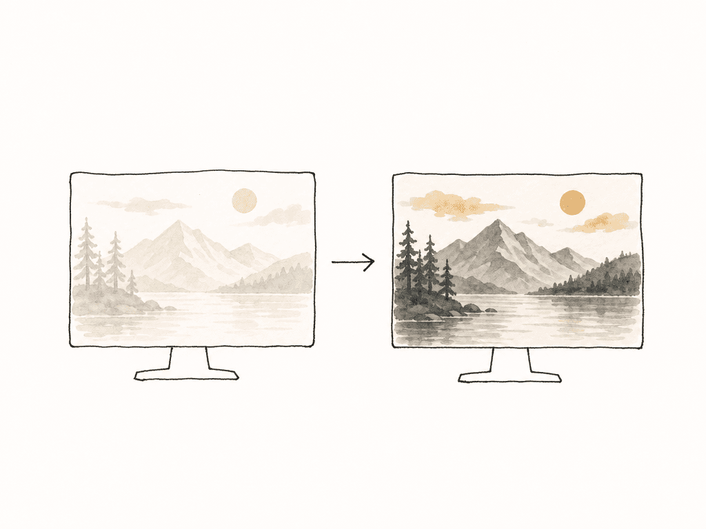
- Record the camera’s preferred acquisition format, usually Log or RAW.
- Convert each feed to the wall’s viewing target for monitoring.
- Keep the monitoring transform out of the recorded camera master unless the production has intentionally chosen to bake it in.
- Label the transform used for every camera feed, especially when different camera brands or models are mixed.
Map the chain before you patch it
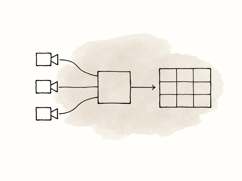
A monitor wall has more places to introduce a mismatch than most teams expect. The camera may output Log or LUT-applied video, while the router may convert formats. A switcher or multiviewer may scale or legalize the signal, and a LUT box, color corrector, or software layer may apply a transform. The wall processor may do its own color management, and each monitor may have its own profile, backlight behavior, and local settings. A typical chain looks like this:- Camera body and lens
- Camera output settings over SDI, HDMI, NDI, ST 2110, SRT, RTSP, or another transport
- Sync, timecode, and frame rate reference
- Router, switcher, multiviewer, or capture system
- Per-camera LUT or live correction stage
- Video wall processor or layout engine
- Individual monitor panels or LED wall modules
- Room lighting and viewing position
Choose the right routing approach
The right routing method depends on distance, latency tolerance, number of feeds, and how much the wall needs to behave like a broadcast engineering system versus a conference-room confidence display.| Routing approach | Best fit | Strengths | Risks to manage |
|---|---|---|---|
| SDI | Stages, trucks, control rooms, DIT areas, and post supervision bays | Predictable long runs with embedded audio, timecode, routers, multiviewers, recorders, and sync infrastructure | Format or LUT mismatches can still occur if cameras, converters, or processors are set differently |
| HDMI | Short temporary runs with nearby cameras and smaller setups | Simple point-to-point cabling for compact monitor walls | Cable length, EDID negotiation, consumer range settings, and connector reliability |
| Network video | Designed IP facilities, remote feeds, and flexible routing environments | Scales across locations when bandwidth and latency are engineered | Compression, decode latency, congestion, and inconsistent color metadata handling |
- Is the wall for color-critical comparison, or mostly for awareness and framing?
- How many cameras need to appear at once?
- Are feeds local, remote, or mixed?
- Can the network guarantee bandwidth and latency under load?
- Does every feed arrive in the same frame rate, resolution, range, and color encoding?
- Does the video engineer need to route cameras dynamically during the session?
Match cameras before the wall tries to help
A monitor wall can't rescue a sloppy camera match. It can only reveal it more clearly. Start with the cameras. Match frame rate, shutter, white balance, ISO or EI strategy, picture profile, and output format. If possible, use the same camera model across angles. If not, at least group cameras by color science and dynamic range. Mixing a cinema camera in Log with a mirrorless camera in Rec.709 and a phone in its own Log format can work, but only if you give every source the correct input transform. One common failure is mixing gamma curves casually. A camera recording Rec.709 may clip highlights that a Log camera retains. No LUT on the monitor wall can recover information that was never captured. Another failure is assuming that two cameras from the same brand match automatically. Different sensors, DSP pipelines, lenses, internal noise reduction, and highlight rolloff can make “same brand” feeds visibly different. Use a color chart and gray card under the real production lighting. Put every camera on the same chart, expose consistently, and look at waveform and vectorscope, not just the wall. The waveform will show whether gray scale and exposure are aligned. The vectorscope will show hue and saturation differences that your eye may forgive in isolation but notice immediately on a wall. Your team should build or select per-camera LUTs from that test. For a simple setup, that might mean manufacturer Log-to-709 LUTs plus small trims. For a higher-end setup, it might mean a show LUT per camera family, with CDL or live correction on top. The goal is to make cuts and comparisons feel continuous under the real lighting and lens choices.Apply per-camera LUTs before the wall layout
The cleanest place to apply LUTs is before the signal becomes a tile in the wall. Think of each feed as needing its own input transform. Once you normalize the feeds, the wall processor can worry about layout, scaling, labels, tally, and routing. If you apply one global LUT to the entire wall output, it only works when every camera feed has the same input color space and exposure behavior. That's rare in mixed-camera production. A global display transform can be useful at the very end, but camera-specific transforms belong earlier.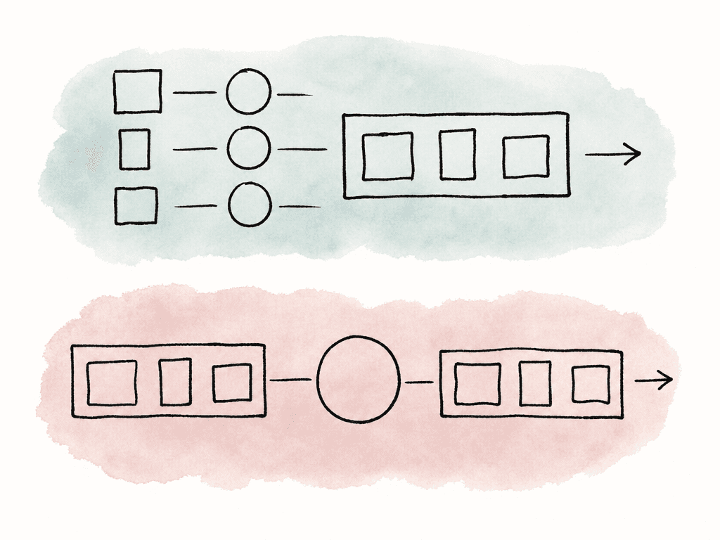
- Camera name or angle label
- Input color space and gamma
- Monitoring LUT or transform name
- Any CDL, white balance trim, or live correction values
- Output target for the wall
- Whether you're also recording the feed at that stage
Calibrate the wall as its own display system
Even perfectly matched feeds will look wrong on an uncalibrated wall. Multi-monitor walls often suffer from the “patchwork” effect: one tile is slightly magenta, another is dimmer, another has a cooler white point, and the whole wall changes after it warms up.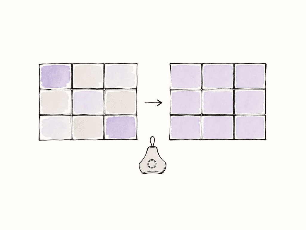
- Visual matching, where an experienced video engineer adjusts panels using test patterns and reference images.
- Sensor-based point measurement, where a probe measures selected patches on each display.
- Camera-based area measurement, where a calibrated camera measures the wall surface to detect panel-to-panel variation.
Control the room
A calibrated wall in an unstable room will still mislead people. Daylight, reflections, colored set pieces, desk lamps, and panel temperature all affect perception. So does viewer adaptation. A wall that looks neutral at 9 a.m. can appear warm or cool later if the environment changes around it. You don't need a full grading suite for every monitor wall, but you do need consistency. Keep direct sunlight off the screens. Avoid strongly colored light near the wall. Let displays warm up before matching. Don't let one monitor run in a different eco mode because someone wanted it dimmer yesterday. If your team uses the wall for camera shading or color review, treat room changes as part of the color pipeline. Viewing angle also matters. LCD panels can shift color and contrast off-axis. If the director, DP, and producer are all judging from different positions, they may literally be seeing different images. For color-sensitive work, define the primary viewing position and calibrate for that reality.Watch latency and sync
Color consistency is only part of trust. A monitor wall also has to preserve timing well enough for the job. For directing and client review, a small amount of latency may be acceptable if the system delays all feeds equally. For camera shading, live switching, performance capture, and stage work, mismatched latency becomes a real problem. The video engineer may compare a face on Camera A against the same face on Camera B and mistake motion timing for exposure or color change. Audio sync can also make one angle feel “wrong” even when the image is fine. Keep frame rates and shutter settings consistent across cameras unless there's a creative reason not to. Use genlock when the production requires tight camera sync. In LED wall or virtual production environments, sync becomes more serious because the camera sensor, LED processor, refresh behavior, and shutter all interact. A wall can look great to the eye and still produce banding, flicker, color shifts, or moiré under camera. LED walls need camera-specific testing. Refresh rate claims alone aren't enough. Test the actual camera, lens, shutter angle, distance, processor settings, and content. If the wall sits behind talent and also appears on the monitor wall, you're managing two viewing problems at once: how the camera captures the LED wall, and how the production team views the camera feed.Build layouts for the work people are doing
A monitor wall layout should reflect the decisions people need to make. A director may want all angles visible with program large. A DP may want camera feeds equal-sized with scopes nearby. An editor may want camera labels, timecode, and record status. A post supervisor may want confidence feeds plus playback or remote review. Common wall layouts include:- Equal tiles for camera comparison
- Program large with camera previews around it
- One camera per physical monitor for shading
- Multiview on a single large display in tight spaces
- Camera feeds grouped by unit, location, or scene
- Technical view with scopes, router status, and recording indicators
Common failure modes and where to look
When the wall looks wrong, isolate the chain instead of tweaking randomly. Most problems fall into a few repeatable categories. Here are the usual symptoms and likely causes:- One camera is flat and washed out: the system is displaying a Log feed without a viewing transform.
- One camera is overly contrasty or saturated: the system may be applying a LUT twice, or the camera is outputting Rec.709 into a Log transform.
- One tile is warmer than every other tile: monitor panel calibration, white point, or local picture settings may differ.
- All cameras look wrong on one physical screen: the display or wall processor output is the likely issue, not the cameras.
- The same camera looks different in two places: routing paths aren't equivalent, or one destination applies extra processing.
- Skin tones match on the wall but not in post: the team didn't document monitoring LUTs, metadata, or camera recording settings.
- Banding or flicker appears under camera on an LED wall: your team needs to test refresh, shutter, genlock, PWM dimming, or scan interaction.
Document the setup so post can trust it
A multi-camera wall is part of the production record. It influences exposure, client approvals, continuity notes, editorial confidence, and sometimes live color decisions. If the setup is undocumented, the wall becomes hearsay. Capture the essentials:- camera models, recording formats, and output formats
- LUT names
- wall target color space
- monitor calibration target and routing diagram
- any per-camera trims
The setup rule that keeps the wall honest
A consistent multi-camera monitor wall comes from separating three jobs: camera matching, signal transformation, and display calibration. Match the cameras under the real lighting. Apply the right LUT or transform per camera before layout. Calibrate the wall so every tile shows the same target image. Then keep the room, routing, and metadata stable enough that people can trust what they see. If a wall is only for awareness, you can relax some of this. If the wall is driving exposure, shading, client approval, or editorial decisions, don't rely on eyeballing a stack of mismatched displays. Build the chain deliberately, label it clearly, and verify problems by stage instead of guessing from the couch.FAQ
Apply per-camera LUTs before the feeds are arranged into the wall layout. Each camera should be normalized from its own Log, RAW monitoring output, or camera color space into the wall viewing target first. After that, the wall processor can handle scaling, labels, borders, tally, and layout without trying to solve camera-specific color differences.
A single global LUT only works reliably when every camera feed uses the same input color space, gamma, exposure behavior, and monitoring path. In mixed-camera workflows, each camera usually needs its own input transform or correction before the wall layout. A global display transform may still be useful at the end, but it shouldn't replace camera-specific transforms.
Cameras from the same brand can still differ because of sensor design, internal processing, lens choice, noise reduction, highlight handling, and exposure strategy. A manufacturer LUT is only a starting point. For closer matching, shoot a color chart and gray card under the real lighting, compare the feeds with waveform and vectorscope, then apply per-camera trims or CDLs as needed.
Swap the feed to a different tile or display. If the problem follows the camera feed, the issue is upstream, such as camera settings, LUTs, routing, or processing. If the problem stays on the same physical screen, the likely cause is display calibration, wall processor output, monitor settings, or a panel issue.
For standard Rec.709 monitoring, common targets include a D65 white point, gamma 2.4 for dim viewing environments, and a consistent luminance level appropriate to the room. The exact brightness target depends on the environment and display type, but the key is that every panel or tile is matched to the same target with automatic brightness, dynamic contrast, eco modes, and color enhancements disabled.
Create fields for camera ID, input color space, monitoring LUT, CDL values, wall target, and calibration date, then attach that information to the relevant test clips, stills, or camera reports. Aspect lets teams add structured custom metadata, which makes LUT and wall setup details searchable later.


